
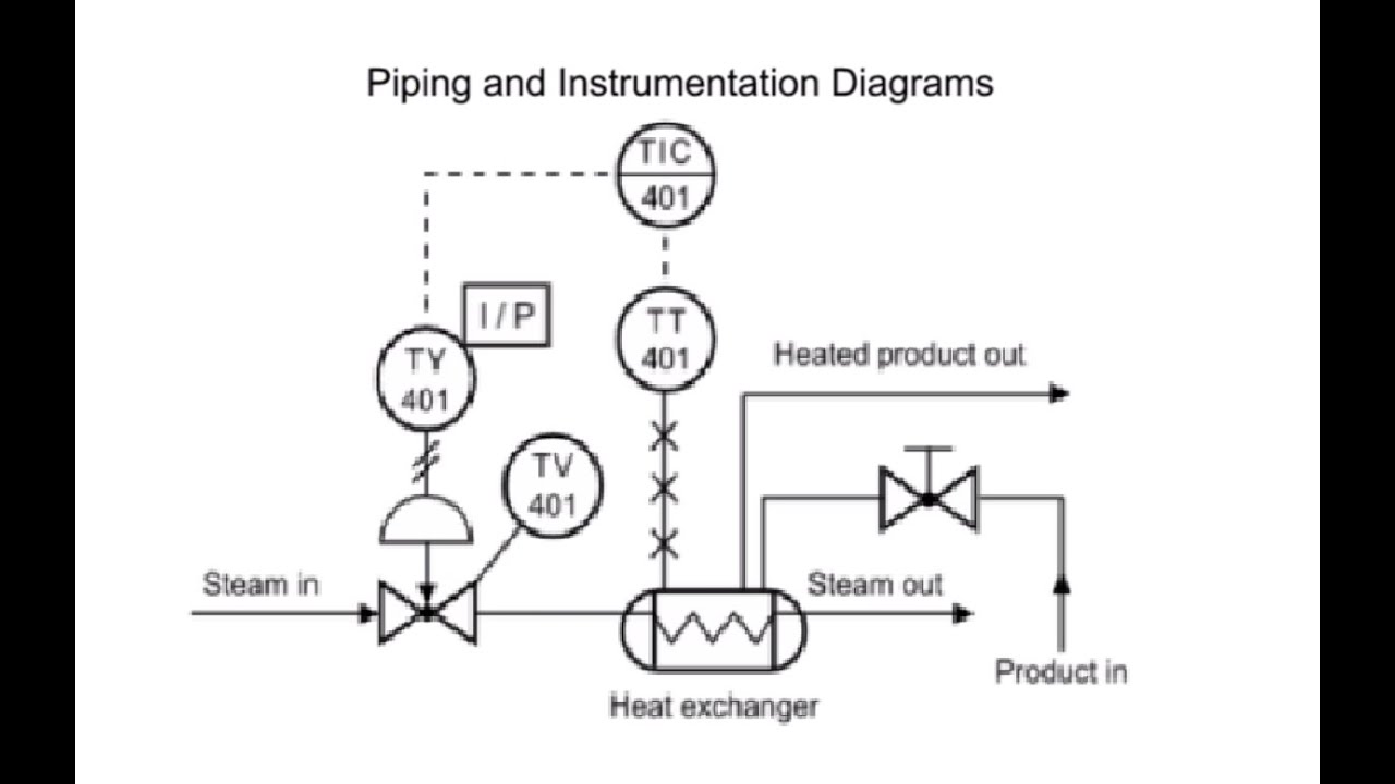
A PID is a two-dimensional 2D diagram that contains the engineering details about a designs piping and instrumentation components. All globe valves shall be normally installed with flow under seat.

Coriolis Piping And Instrumentation Diagram P Id Diagram Diagram
The PIDs are used to operate process systems.

. P. Every shape can be edited and rearranged. Names and numbers of mechanical equipment.
For ventilation notes see g h drawing 11485-m-76. For exceptionsrefer to notes on piping orawings an0 g 6. Learn more about SmartDraw class diagram maker.
PID is the abbreviation for piping and instrumentation drawing. A PID includes information about the following. In the Layer State drop-down list click Manage Layer States.
Learn How to Read PID from the expert. Just drag them into the view and start your work. Reading or tracing a PID drawing to understand the process or design requirements are quite easy if the PID symbols are properly understood.
So it is always preferable to go through the PID symbols repeatedly those are provided in the initial 4-5 pages of the PID sets. Works on Any Device Use SmartDraw. The Layer States Manager is also accessible from the Layer Properties Manager.
Because of this a large amount of the symbology appearing on PIDs depicts instrumentation and instrument loops. Ventilation - Systems for ventilation and air handling - air change rates ducts and pressure drops charts and diagrams and more. 2D Schematic Drawings - Create and share online schematic PID HVAC Process Flow diagrams and drawings - using templates with Google Docs.
The new interface is focused on the content and allows you to maximize your drawing areas. Click this link for detailed information about Chemical Equation Shapes and Symbols. Subscribe -httpsgoogl9OktFA You will learn how to read PID and PEFS with the help of the actual plant drawingW.
The Chemical Equation Drawing Software includes some pre-defined molecular shapes. -drawing to refer to for continuation - throttle valve. Once that is ready open the PID and start reading it.
Mechanical equipment with names and numbers. Top Features of Edraw Laboratory Equipment Drawing Software 1. An improved and user-friendly interface based on the feedback from years of experience.
The shapes are able to modify bond and angles of side chains. Click Home tab Layers panel Layer State. Drawing Tools - 2D and 3D engineering drawing tools.
In the Select Layer States dialog box choose a layer. A PID should include. In the Import Layer State dialog box open a file with a dwg dws or dwt file name extension.
All valves and their. One of the main purposes of a PID is to provide functional information about how instrumentation in a system or piece of equipment interfaces with the system or piece of equipment. Oamper with fuse link.
Libraries can now float and can be individually enabled and disabled. In the Layer States Manager click Import. PIDs shows all piping including physical sequences of branches reducers valves equipment instrumentation and control interlocks.
Intelligent Formatting Add or remove a shape and our UML diagram software realigns and arranges all the elements so that everything looks great.

Pfd And P Id Piping And Instrumentation Diagram Basic Concepts Process Flow

P Id Flow System Example P Id Diagram Piping And Instrumentation Diagram Example

Pin Di Hydraulics

Interview Tips Piping And Instrumentation Diagram Process Flow Diagram P Id Diagram

A Process Flow Diagram Shows The Relationships Between The Major Equipment S Columns Ves Process Flow Diagram Process Flow Piping And Instrumentation Diagram

What Is Piping And Instrumentation Diagram P Id Inst Tools Piping And Instrumentation Diagram Diagram Education Humor
Draw P Id Diagrams Online In The Browser With Google Docs P Id Diagram Diagram Online Drawing

Gambar Piping Instrumentation Diagram Dan Penjelasannya Diagram

Piping And Instrumentation Documents Instrumentation Tools Piping And Instrumentation Diagram P Id Diagram Mechanical Engineering Design

What Is A P Id Diagram In Laymen S Term Realpars P Id Diagram Diagram Piping And Instrumentation Diagram

Piping And Instrumentation Diagram P Id Piping And Instrumentation Diagram P Id Diagram Chemical Engineering Projects
How To Read Piping And Instrumentation Diagram P Id Piping And Instrumentation Diagram P Id Diagram Diagram

Plc Control System Control Systems Engineering Control Engineering Piping And Instrumentation Diagram

P Id Flow System Example P Id Diagram Piping And Instrumentation Diagram Example

Pin On Instrumentation Tools

P Id Guidelines For Centrifugal Compressor Systems Centrifugal Compressor Compressor P Id Diagram

What Is A P Id Diagram In Laymen S Term Realpars P Id Diagram Diagram Symbols

Flowchart Maker How To Read Piping And Instrumentation Diagram Piping And Instrumentation Diagram Diagram P Id Diagram

Piping And Instrumentation Diagram P Id Software Piping And Instrumentation Diagram P Id Diagram Id Software


